Raman Amplifiers Use Span Fiber to Raise Signal Strength
By: Andrew Stentz, Torben Nielsen, and Per Hansen, <%=company%>
Contents
Gain across the entire window
Amplification in the transmission fiber
Benefits of Raman
Novel optical amplifiers are needed to allow lightwave communication systems to expand beyond the capabilities of conventional erbium-doped fiber amplifiers. Raman amplifiers are excellent candidates to serve this role since they are effective both as distributed and discrete amplifiers, and can be tuned to any wavelength in the transmission window of optical fibers.
Stimulated Raman scattering is a nonlinear optical process in which intense pump light interacts with a signal of lower frequency, simultaneously amplifying the signal and producing an optical phonon.1 Raman scattering occurs in all optical fibers with its strength depending only on the type of optical fiber and the frequency offset and power of the interacting waves.
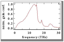
In 1972, R. H. Stolen and E. P. Ippen2 measured the Raman gain spectra of silica fibers (see Figure 1). Note that the maximum gain occurs for a frequency offset between the pump and signal of 13.2 THz (a wavelength shift of 60 to 100 nm in the near infrared). A more detailed explanation of Raman scattering in fused silica can be found in the work of Galeener. 3

Gain across the entire window
Since the Raman gain spectrum is not locked to fixed energy levels as are rare-earth elements, such as erbium, Raman gain can be generated at any wavelength in the infrared, as long as the requisite pump light is available. This feature allows Raman amplification to be applied across the entire transmission window of silica optical fibers.
Thus far, discrete Raman amplifiers have been demonstrated at 1.3, 1.4, and 1.5 µm. They have been designed, constructed and tested as high-gain, low-noise optical preamplifiers4 for dense-wavelength-division-multiplexed (DWDM) digital transmission systems and as high-power, analog amplifiers at 1.3 µm.5 To the best of our knowledge, the amplifier described in Ref. 5 is the only analog-grade, silica-fiber amplifier to be demonstrated at 1.3 µm.
Raman amplifiers have also made possible the demonstration of a DWDM transmission system over AllWave fiber in the newly opened transmission window at 1.4 µm. 6
Amplification in the transmission fiber
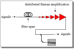
Since Raman gain occurs in all optical fibers, even installed transmission fibers can be made to amplify communication signals by injecting pump light into the fiber span. In essence, the transmission fiber itself becomes the amplifier medium. Launching pump light into the end of the transmission span and allowing it to counter-propagate relative to the signals triggers distributed Raman amplification (see Figure 2), which can greatly enhance the performance of communication systems.

By amplifying signals within a span before signal-to-noise ratios fall to an unacceptable level, distributed Raman amplification can increase the signal-to-noise ratio of the output signals. This effect was characterized by Hansen et al. in 1998, where it was shown that Raman amplifiers may actually have negative effective noise figures. 7
Benefits of Raman
Distributed Raman amplification can counteract the effects of higher-loss spans, to increase the capacity of a communication system, or to reduce the maximum signal powers within a communication system in order to reduce optical nonlinearities. An experiment involving the latter application showed that distributed Raman amplification could permit dense wavelength division multiplexing (DWDM) transmission over zero-dispersion dispersion-shifted fiber about the zero-dispersion wavelength of the fiber.8
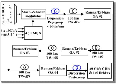
In a recent demonstration of the power of distributed Raman amplification, 40 wavelengths, each carrying 40 Gb/s, were transmitted over four spans of 100 km of TrueWave Reduced Slope fiber using distributed Raman amplification (see Figure 3). 9 To the best of our knowledge, this is the first demonstration of a 40 Gb/s transmission system operating over multiple spans of 80 to 100 km length without the use of optical time-division multiplexing. This experiment demonstrates a record spectral efficiency of 0.4 b/s/Hz and a record span loss of 21 dB at 40 Gb/s.

Four 10 Gb/s tributaries, each encoded with a 231 – 1 PRBS sequence, are electrically multiplexed to 40 Gb/s. A Mach-Zehnder modulator impressed these bit streams upon forty 100-GHz-spaced wavelength division multiplexed channels from 1530.7 to 1561.8 nm. Before launch into the fiber spans, the channels pass through –40 ps/nm of dispersion-compensating fiber for pre-compensation and decorrelation. At the end of the transmission spans, the channels are post-compensated and fed to the 40 Gb/s carrier-data-recovery circuit and 1:4 demultiplexer for bit-error-rate measurements.
Four sets of hybrid Raman/erbium-doped fiber amplifiers boost the signal strength. These amplifiers provide 23 dB of peak Raman gain and contain gain-flattening filters that flatten the composite gain spectrum to within 1 dB over the signal bandwidth. The equivalent noise figure of the hybrid amplifiers ranges from –0.3 to –1.5 dB over the signal bandwidth. This low noise figure makes possible the reduction of the launched signal power to –1 dBm per channel, eliminating penalties from optical nonlinearities.
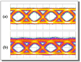
The pre- and post-transmission eye diagrams show good signal fidelity. The optical signal-to-noise ratios (OSNR) measured after transmission through 4 x 100 km of fiber were better than 30 dB. The worst-case Q-value was 16.1 dB, corresponding to a bit-error rate of 9x10-11.

Certainly as communication systems are pushed beyond the limits of conventional erbium-doped fiber amplifiers, Raman amplifiers will play an increasingly important role to extend the capability of existing systems and usher in new generations of communication systems with increasing capacity and performance.
References:
1. G.P. Agrawal, Nonlinear Fiber Optics, Academic Press, San Diego, (1995).
2. R.H. Stolen and E.P. Ippen, "Raman gain in glass optical waveguides," Appl. Phys. Lett., 22, p. 276, (1973).
3. F.L. Galeener, et. al., "Comparison of the neutron, Raman, and infrared vibrational spectra of vitreous SiO2, GeO2, and BeF2," Phys. Rev. B, 27, p. 1052, (1983).
4. T.N. Nielsen, et. al., "8x10 Gb/s 1.3 µm unrepeatered transmission over a distance of 141 km with Raman post- and pre-amplifiers," IEEE Photon. Technol. Lett., 10, p. 1492, (1998).
5. A.J. Stentz, et. al., "Raman Ring Amplifier at 1.3 mm with Analog-Grade Noise Performance and an Output Power of 23 dBm," Opt. Fib. Commun. Conf., #PD16, San Jose CA, (1996).
6. A.K. Srivastava, et. al., "High speed WDM transmission in AllWave fiber in both the 1.4 µm and 1.55 µm bands," OAA '98, #PD2, Vail, Colorado, July, (1998).
7. P.B. Hansen, et. al., "Rayleigh scattering limitations in distributed Raman pre-amplifiers," IEEE Photon. Technol. Lett., 10, p. 159, (1998).
8. P.B. Hansen, et. al., "Dense wavelength-division multiplexed transmission in 'zero-dispersion' DSF by means of hybrid Raman/erbium-doped fiber amplifiers," Opt. Fib. Commun. Conf., #PD8, San Diego, (1999).
9. T.N. Nielsen, et. al., "1.6 Tb/s (40x40 Gb/s) transmission over 4x100km nonzero-dispersion fiber using hybrid Raman/erbium-doped inline amplifiers," Europ. Conf. on Opt. Commun., #PD2-2, Nice, FR, (1999).
About the authors…
Andrew Stentz, Torben Nielsen and Per Hansen are with Bell Laboratories, Lucent Technologies, 600 Mountain Ave., Murray Hill, NJ 07974. E-mail: stentz@lucent.com.
